One of the ATL improvements discussed in this storyline was improving the ergonomics in the Lightning's cockpit. That includes the engine management controls as well as the placement of the secondary flight controls and instrumentation. Greg from Greg's Airplanes and Automobiles has recently post 3 new videos that examines the improving of cockpit ergonomics in several WW2 fighters. Though the P-38 is not examined in these videos the design concepts discussed may be of interest. I'm including a link to a website that will provide an excellent scrollable close-up of a P-38L cockpit. It's interesting to compare the P-38's cockpit layout to other fighters with an eye as to how best to improve the P-38's cockpit layout.
You are using an out of date browser. It may not display this or other websites correctly.
You should upgrade or use an alternative browser.
You should upgrade or use an alternative browser.
Threadmarks
View all 52 threadmarks
Reader mode
Reader mode
Recent threadmarks
Ch.36(b) - The Reich Strikes Back (15 Aug 1944) Ch.37 - Compound Magic (6 Sep 1944) Recap of P-38 Modifications to Date (Autumn 1944) Ch.16a - Diagram of Modified Fuel System Ch.38(a) - Long Legged Leyte (24 Oct 1944) Ch.38(b) - Leyte of the Night (24-25 Oct 1944) Ch.38(c) - Goodbye Fair Leyte (26 Oct 1944) Ch.38(d) - Addendum: Battle East of Samar After Action SummaryLets go back to take a look at the OTL development of the P-38 by going right back to the very beginning. And we'll be taking a new look at that old question, why a twin boom design? And to help put things into better perspective here is a link to Greg's video discussing this subject. The link runs the video at the most pertinent part for my post but it's worth watching the whole video as it's pretty good.
 From Wikipedia's P-38 article.
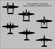
There were really only two practical choices for Kelly Johnston out of the original six concepts. Kelly Johnson went with the twin boom design instead of the conventional twin engine single fuselage design because of the length required of the engine nacelles with all the components that needed to be packed in. Most especially the radiators. But what if the engine nacelles had only needed to be made long enough to contain the landing gear?
The Prestone radiators had to be fitted somewhere of course. Why not in the leading edge of the wing centre section? Would Kelly Johnson have known about that option in 1938? When done correctly putting radiators and oil coolers in the wing leading edge is an effective and low drag installation. When did aircraft designers first do this?
Before 1938 or 39? For example Bell Aircraft put the oil cooler and radiator in the left and right leading edge of their P-39s' wings when first built with its turbocharger.
While considering which design path to choose what if Kelly Johnson had realized, "we can place those Prestone radiators in the wing leading edge"* and gone that route?
Then there would've been no reason to extend the engine nacelles longer then was needed to fit the landing gear. Would Johnson have still chosen the twin boom design? The other smaller components like the oxygen bottles, battery and the magcompass remote would have fitted easily into a larger single fuselage.
A further serendipitous possibility is if Lockheed's design team decides to extends the centre section wings' leading edge to make more room for the radiators thereby inadvertently increasing the P-38s critical Mach number and greatly reducing the compressibility tuck problem.
Back in 1938 when Kelly Johnson was pondering which design to select to build the XP-38 interceptor I wonder if he knew about and had considered the other radiator location options.
* This is a fictional quote.
The designers may have been aware of such an option but with the "current" wing design, NACA 23016, installing rads in the leading edge would have removed most of the space for the forward (Reserve) fuel tanks. The option, in that case, would have amounted to the 1942 NACA recommendation of extending the leading edge forward enough to accommodate the radiators and associated plumbing/controls, resulting in something very close to the center-wing section used in this timeline....snip...
Back in 1938 when Kelly Johnson was pondering which design to select to build the XP-38 interceptor I wonder if he knew about and had considered the other radiator location options.
Here is a drawing I did some years ago showing how such a nacelle could have looked:
As you can see, without making additional changes, especially to the landing gear arrangement, the nacelle is still quite long. One solution may have been to have inward folding gear and adding fuel tanks in the the nacelle but I'm not sure what the net effect in fuel capacity and weight-and-balance would be. I'd have to look into more.
EDIT: I suppose another option could be to increase the fuselage height aft of the cockpit and provide a large main fuselage tank directly behind the pilot. That would keep it close to CoG for balance and allow enough room in the wing for inward folding gear (which would also help with minimized weight-and-balance shift with gear up vs gear down.
Last edited:
"The designers may have been aware of such an option but with the "current" wing design, NACA 23016, installing rads in the leading edge would have removed most of the space for the forward (Reserve) fuel tanks. The option, in that case, would have amounted to the 1942 NACA recommendation of extending the leading edge forward enough to accommodate the radiators and associated plumbing/controls, resulting in something very close to the center-wing section used in this timeline."The designers may have been aware of such an option but with the "current" wing design, NACA 23016, installing rads in the leading edge would have removed most of the space for the forward (Reserve) fuel tanks. The option, in that case, would have amounted to the 1942 NACA recommendation of extending the leading edge forward enough to accommodate the radiators and associated plumbing/controls, resulting in something very close to the center-wing section used in this timeline.
Here is a drawing I did some years ago showing how such a nacelle could have looked:
View attachment 900130
As you can see, without making additional changes, especially to the landing gear arrangement, the nacelle is still quite long. One solution may have been to have inward folding gear and adding fuel tanks in the the nacelle but I'm not sure what the net effect in fuel capacity and weight-and-balance would be. I'd have to look into more.
EDIT: I suppose another option could be to increase the fuselage height aft of the cockpit and provide a large main fuselage tank directly behind the pilot. That would keep it close to CoG for balance and allow enough room in the wing for inward folding gear (which would also help with minimized weight-and-balance shift with gear up vs gear down.
Which could have meant Lockheed's designers stumbling unto the fix for Mach tuck before they knew there was such a thing. Or at least greatly ameliorated it. Looking at your drawing (great drawing BTW) it's clear the engine nacelles would still be quite long. I don't think they could have more sharply tapered the nacelle rear without creating more drag there. But, OTOH so what it the engine nacelles are long? Might look a bit funny but is it a crippling problem?
If Wikipedia is to be believed the first flight of the P-39 occurred on April 6th 1938. So at least as far back as 1937 the idea of locating radiators and oil coolers in wing leading edges existed. And somebody was building the rectangular shaped radiators and oil coolers that could fit in the P-39s' leading edge. Whether Kelly Johnson and the design team at Lockheed were aware of this while designing the XP-38 is the question.
If they had decided to go with the inward folding landing gear to reduce engine nacelle length then to restore the reduced fuel load that would have caused put fuel tanks in the outer wings. This might have prompted Lockheed to use a better system for intercooling. Isn't speculation fun?
Last edited:
Now you've got me down a rabbit-hole. If they could redesign the gear to be at least partially inward swinging, then they could shorten the nacelle. There is plenty of room in the fuselage (with some minor rearranging like moving hydraulic reservoir aft) for two 150 gal tanks behind the cockpit. The need to streamline the aft nacelles a little could lead to an alteration in the turbo layout/installation. Something like this:

There is room around the main turbo outlet for additional ducting to improve cooling airflow over the turbo's and this arrangement shouldn't produce too much back pressure on the turbos.
EDIT: Also of note is that the fuselage would likely have to be enlarged slightly so they can beef up the junction to the empennage. I could see this current design leading to tails breaking off under high-G pull outs.
Last edited:
Turbocharger relocation eh. I've got an idea or two about that too. If Kelly Johnson had decided to put the radiators and oil coolers in the wings' leading edge it opens up some other possibilities. Since this could've happened early in the design stage when everything is still on paper and they're just starting to work up and assemble the wings I think they'd have quite a bit of flexibility.Now you've got me down a rabbit-hole. If they could redesign the gear to be at least partially inward swinging, then they could shorten the nacelle. There is plenty of room in the fuselage (with some minor rearranging like moving hydraulic reservoir aft) for two 150 gal tanks behind the cockpit. The need to streamline the aft nacelles a little could lead to an alteration in the turbo layout/installation. Something like this:
View attachment 900149
There is room around the main turbo outlet for additional ducting to improve cooling airflow over the turbo's and this arrangement shouldn't produce too much back pressure on the turbos.
EDIT: Also of note is that the fuselage would likely have to be enlarged slightly so they can beef up the junction to the empennage. I could see this current design leading to tails breaking off under high-G pull outs.
With no oil coolers located in the engine nacelles that frees up enough space for fitting the turbochargers at the bottom of the nacelles between the rear of the engine and in front of the landing gear bay. Similar to the way Bell fitted the turbocharger in the P-39 under the engine. With the turbine extending slightly into airflow. Some kind of drag reducing and protective cover could be developed later as was done for the P-47. If the cover and surrounding housing is designed correctly the propwash airflow could induce a reduced air pressure at the rear of the cover reducing back pressure and enhancing the turbine efficiency.
Locating the turbochargers just behind the engine and below the engine mount would shorten the exhaust piping. Reducing weight and simplifying the job of cooling the piping and surrounding structure. It also reduces the length of the compressed air ducting from the turbocharger to the intercooler and then on to the carburetors. A more simplified and lighter installation.
Ideally if the Lockheed design team has seen the advantages of leading edge mounted radiators they may reconsider they original OTL choice for the inadequate and unregulated pipe intercooler. With the pipe intercooler the only way to avoid excess charge air temperature was by throttling back thus reducing the boost. For too low CAT a pilot had no option. I think this contributed to the crash of the XP-38 due to carburetor icing. This would later affect P-38s in the cold Winters skies over Europe.
Fitting a box type heat exchanger intercooler at the leading edge root of the outer wings would have given the P-38 a more capable and more regulated intercooler right at the beginning of the P-38 program. Similar to the radiators and oil coolers the exit flow through the cold side of the heat exchanger section of the intercooler would be controlled by a cowl flap. If Lockheed is contracting out to suppliers to build rectangular radiators these same suppliers could design and build an intercooler to fit in the outer wing leading edge at the wing root. I don't think it would've been necessary to extend the leading edge of the outer wing to accommodate the intercooler.
If there are then no major components in the engine nacelles from the rear wing spar backwards to the end of the nacelles other then the landing gear and gear door hydraulics then maybe the rear of the engine nacelle can be tapered a little more narrowly from the wing trailing edge to the nacelles tip. Might reduce the length a little as well as the wetted area and weight.
Perhaps all these speculations are weighing a little too heavily on the benefits of the golden 20/20 hindsight. However I'm starting to think the biggest event in the OTL P-38 saga wasn't Lt. Kelseys crash landing the XP-38 but Kelly Johnson and company's unawareness or for unknow reasons reluctance to utilize the concept of putting the various coolers and radiators in the wing leading edges. An approach that was used by Bell Aircraft in 1937 and was also used in some very successful airplanes later in WW2.
Another OTL P-38 mystery.
Last edited:
Yeah, I didn't relocate the oil coolers in my above design so I kept the turbos aft of the wing rear spar--in fact in rotation I moved them behind the wing trailing edge entirely. I initially kept them slightly further forward with them attached to the rear spar but the nacelle was then too short for effective streamlining. It just didn't look right.
If we were free up space beneath the engines a local installation of the turbos like @Draconis described, rather than remote, could be possible. The other alternative would be to reduce nacelle frontal area, keep the top mounted turbo as OTL, but allow a more streamlined aft section of the nacelle for improved rejoining of the airflow and associated drag reduction.
If we were free up space beneath the engines a local installation of the turbos like @Draconis described, rather than remote, could be possible. The other alternative would be to reduce nacelle frontal area, keep the top mounted turbo as OTL, but allow a more streamlined aft section of the nacelle for improved rejoining of the airflow and associated drag reduction.
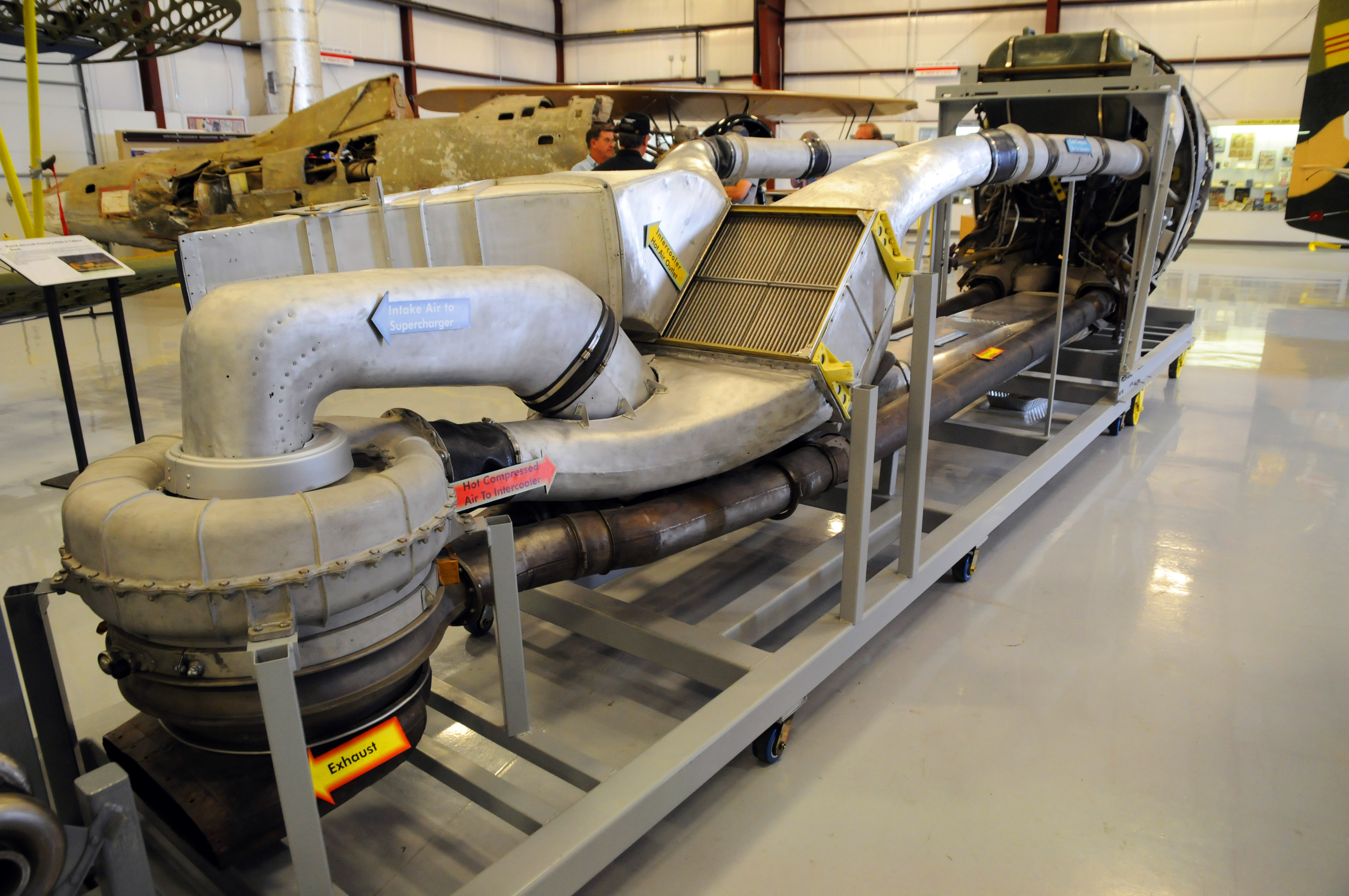
One thing to be careful of here is that my understanding of the early turbos is that they were running right on the material limits and needed the exhaust gas to be cooled somewhat before it reached them to operate safely. Hence putting the turbos distant from the engine, allowing the gases to cool down in the ducting. There's chapter and verse on it in The Secret Horsepower Race, but I can't be bothered to dig into it this morning (sorry!). The Thunderbolt installation below gives you some idea of the complexity they ended up with.If we were free up space beneath the engines a local installation of the turbos like @Draconis described, rather than remote, could be possible. The other alternative would be to reduce nacelle frontal area, keep the top mounted turbo as OTL, but allow a more streamlined aft section of the nacelle for improved rejoining of the airflow and associated drag reduction.
Basic turbine blade cooling is probably feasible - the Jumo 004 used it because of the terrible alloys they were forced to work with - and that would probably be enough to let them fit the turbine directly onto the exhaust. To the best of my knowledge the US never implemented this during the war however, so that's going to take a while to implement.
The other thing to consider is taking a leaf out of the DB-605 design and having one turbocharger per cylinder bank (supercharger in the case of the DB-605). That would help a bit with packaging and I think (brain not working properly yet) should reduce the stress in the turbine wheel a bit as you halve the gas flow and so reduce the blade tip diameter a bit.

Last edited:
So now I've started to go down a turbo- and super-charger rabbit-hole this morning. Wahey.
There are a whole bunch of interlocking problems, and I'm wondering if the technology for a very good solution to them existed in the form of the swirl throttle, invented by Szydlowski and Planiol in 1937 for the Hispano-Suiza 12Y.
Getting the same effect (to a lower standard) with a Szydlowski-type swirl throttle would allow the use of a constant gear ratio gearbox, simplify the compressor design (no need for a concentric shaft) and simplify the packaging. The OTL -127 gave about 2300 HP military power and over 3,000 with water/methanol injection - so achieving 2,000 HP with intercooling by 1942 or so seems practicable.
So essentially the idea is to remove the small supercharger fitted to the rear of the engine, attach the existing turbocharger from the Lightning to it (the supercharger shaft was an 8:1 gear ratio giving 24,000 RPM at maximum speed, the same as some GE turbochargers such as the B-22 and B-31), fix the wastegate closed and fit a swirl throttle at the compressor inlet. An air-to-glycol heat exchanger would also be fitted between the compressor outlet and carburettor for charge cooling.
This would all need to be done by GE due to the way the US divided up responsibility for engine and turbocharger, but it isn't outlandish. Everything except the throttle is a stock item, and the V-1710 modularity should make testing this out relatively easy.
There are a whole bunch of interlocking problems, and I'm wondering if the technology for a very good solution to them existed in the form of the swirl throttle, invented by Szydlowski and Planiol in 1937 for the Hispano-Suiza 12Y.
- Turbochargers are essentially mandatory for US aircraft - the USAAF was 100% sold on them and had put vast amounts of money into their development. Unfortunately, this led to control issues as it was very hard to manage waste gate control automatically to give correct inlet pressure while managing turbine speed at he time, leading to the risk of over-speeding and disc burst. Superchargers didn't have this issue because they were geared to the engine so had controlled speed and compression ratio.
- Gearing the turbocharger to the engine solves the control issue (it then becomes just like a supercharger) and allows for increased power recovery from the exhaust gases to go to shaft power, but means you're stuck with a single-stage supercharger performance which tends to be pretty dire at altitude.
- Rolls (and later everyone else) got around this problem by fitting a supercharger driven by a two-speed gearbox and/or (depending on model) a clutch mechanism to engage a second compressor stage. This was used with a conventional butterfly throttle which essentially controlled air inlet pressure, with the supercharger gears/stages kicking in when barometric switches said they wouldn't cause knocking.
- The Sydlowski throttle is interesting in that it did two things at the same time - while it acted like a butterfly throttle, it also imparted a lot of swirl to the air going into the centrifugal compressor. Since the compression ratio of a centrifugal compressor is a function of the net amount of tangential velocity added to the air passing through it, adding swirl will reduce the compression ratio rather than (as in the case of a butterfly throttle) choking off the air mass flow to reduce inlet pressure so that the outlet pressure is reduced.
- This essentially widens the operating range of the compressor where it can operate acceptably - probably (in combination with a pressure relief valve on the outlet to avoid over-boosting at low altitude) meaning you can get a single-speed system to work across the whole altitude range. This could be single or dual-stage, although initially single-stage would be a lot easier.
- The first US source I can find writing about this is July 1941, with an engine arriving for test (with support from M. Planiol) at Wright Field by December 1941.
Getting the same effect (to a lower standard) with a Szydlowski-type swirl throttle would allow the use of a constant gear ratio gearbox, simplify the compressor design (no need for a concentric shaft) and simplify the packaging. The OTL -127 gave about 2300 HP military power and over 3,000 with water/methanol injection - so achieving 2,000 HP with intercooling by 1942 or so seems practicable.
So essentially the idea is to remove the small supercharger fitted to the rear of the engine, attach the existing turbocharger from the Lightning to it (the supercharger shaft was an 8:1 gear ratio giving 24,000 RPM at maximum speed, the same as some GE turbochargers such as the B-22 and B-31), fix the wastegate closed and fit a swirl throttle at the compressor inlet. An air-to-glycol heat exchanger would also be fitted between the compressor outlet and carburettor for charge cooling.
This would all need to be done by GE due to the way the US divided up responsibility for engine and turbocharger, but it isn't outlandish. Everything except the throttle is a stock item, and the V-1710 modularity should make testing this out relatively easy.
Last edited:
One thing to be careful of here is that my understanding of the early turbos is that they were running right on the material limits and needed the exhaust gas to be cooled somewhat before it reached them to operate safely. Hence putting the turbos distant from the engine, allowing the gases to cool down in the ducting. There's chapter and verse on it in The Secret Horsepower Race, but I can't be bothered to dig into it this morning (sorry!). The Thunderbolt installation below gives you some idea of the complexity they ended up with.
Good call on the need to have some distance between the cylinders and turbine for the turboes of the early 1940s, indeed for the reasons of skimming that peak temperature form the exhaust gasses.
Basic turbine blade cooling is probably feasible - the Jumo 004 used it because of the terrible alloys they were forced to work with - and that would probably be enough to let them fit the turbine directly onto the exhaust. To the best of my knowledge the US never implemented this during the war however, so that's going to take a while to implement.
The other thing to consider is taking a leaf out of the DB-605 design and having one turbocharger per cylinder bank (supercharger in the case of the DB-605). That would help a bit with packaging and I think (brain not working properly yet) should reduce the stress in the turbine wheel a bit as you halve the gas flow and so reduce the blade tip diameter a bit.
DB 605 was with one S/C per engine, not per engine bank. The layout indeed cut the length on German engines a bit.
DB engines with turboes really never worked great, if at all, and were quite bulky exactly due to the desire to make attain the closely-coupled engine+turbo system.
V-1710 was with the S/C installed just behind the engine (good for pressure ratios of perhaps 2.5:1 to perhaps 3:1 later). On P-38, that S/C was helped out with the turbocharger (upping the pressure ratio to about 5:1, as needed for hi-alt operations). Engine's compression ratio was 6.65:1 during the ww2.
Pressure ratio is usually a feature of compressors, compression ratio is the feature of engines.
Americans seem to 1st thinkered with hollow-bladed turbines at Ford for their V-1650, that was on paper a refined piece of engineering with the 2-stage compressor and without the engine-integral S/C, as well as being DOHC. In reality, the 1st American hollow-blade turbine was on the Wright's turbocharger that went on the Curtiss SC floatplane fighter. About 1000 manufactured (both the turboes and aircraft), none survives today

Rolls (and later everyone else) got around this problem by fitting a supercharger driven by a two-speed gearbox and/or (depending on model) a clutch mechanism to engage a second compressor stage. This was used with a conventional butterfly throttle which essentially controlled air inlet pressure, with the supercharger gears/stages kicking in when barometric switches said they wouldn't cause knocking.
RR's 2-stage superchargers were on the same shaft. Meaning that there was no option of de-clutching the 1st stage (nor the 2nd, closer to the engine), so both stages were turning at same RPM.
RR's concept was copied - too late - by Jumo for the 213E and F, as well as by DB for the 603L and 605L.
P&W did it differently on their 2-stage supercharged engines. The auxiliary S/C (1st stage) had 3 settings: neutral, low, high. In neutral, the ram air was not going through the aux S/C, but was routed directly to carb and the engine-stage S/C. In low setting, the aux impeller was running at lower speed, and ram air was going 1st through it and then through the carb and the engine-stage S/C. Similar with high setting, just this time the aux S/C was turning faster.
Engine-stage S/C was single speed, ie. no possibility to chagne the gears there, and was turning when engine was on.
Allison's 2-stage set-up (used eg. on P-63s and P-82s) was with the engine-stage S/C remaining the 1-speed unit, and the aux stage was run via hydraulic coupling and thus was with variable speed. Both stages were always on when engine was on.
- The Sydlowski throttle is interesting in that it did two things at the same time - while it acted like a butterfly throttle, it also imparted a lot of swirl to the air going into the centrifugal compressor. Since the compression ratio of a centrifugal compressor is a function of the net amount of tangential velocity added to the air passing through it, adding swirl will reduce the compression ratio rather than (as in the case of a butterfly throttle) choking off the air mass flow to reduce inlet pressure so that the outlet pressure is reduced.
- This essentially widens the operating range of the compressor where it can operate acceptably - probably (in combination with a pressure relief valve on the outlet to avoid over-boosting at low altitude) meaning you can get a single-speed system to work across the whole altitude range. This could be single or dual-stage, although initially single-stage would be a lot easier.
- The first US source I can find writing about this is July 1941, with an engine arriving for test (with support from M. Planiol) at Wright Field by December 1941.
French (Turbomeca - company of Mr. Planiol and Syzdlowsky) installed that peculiar system on their supercharger on the HS-12Y engine, that became the -45 (and later the -49 that sacrificed a bit of power down low to gain a bit more above 5 km). The HS-12Y-45 powered the D.520 fighters.
Yes, the improved ways of throttling would've been beneficial for the engines of the day. Install something like that, or the Polikovsky's device (compied by the Germans on the Jumo 213s from the captured Mikulin engines) would've produce a Merlin III with perhaps 1000 HP for take off instead of 880, or 1400-1450 HP down low at +12 psi boost instead of 1300.
I'm not sure that the Turbomeca system was ever operated on a 2-stage engine, or even on the 2-speed 1-stage S/Ced engine. Perhaps test mules?
Not sure. France was separately working on multistage and muti-speed superchargers (NC-C1, C2 and C3 which had three stages for stratospheric bombers) and turbochargers (Rateau and Brown-Boveri) coupled with Hispano systems.French (Turbomeca - company of Mr. Planiol and Syzdlowsky) installed that peculiar system on their supercharger on the HS-12Y engine, that became the -45 (and later the -49 that sacrificed a bit of power down low to gain a bit more above 5 km). The HS-12Y-45 powered the D.520 fighters.
Yes, the improved ways of throttling would've been beneficial for the engines of the day. Install something like that, or the Polikovsky's device (compied by the Germans on the Jumo 213s from the captured Mikulin engines) would've produce a Merlin III with perhaps 1000 HP for take off instead of 880, or 1400-1450 HP down low at +12 psi boost instead of 1300.
I'm not sure that the Turbomeca system was ever operated on a 2-stage engine, or even on the 2-speed 1-stage S/Ced engine. Perhaps test mules?
Not sure. France was separately working on multistage and muti-speed superchargers (NC-C1, C2 and C3 which had three stages for stratospheric bombers) and turbochargers (Rateau and Brown-Boveri) coupled with Hispano systems.
Farman showed (via Flight magazine in May of 1935) the 2-stage S/C system where each stage was geared separately; they were attacking the altitude records already in 1932 with a 2-stage S/Ced engine. Bristol and Junkers were also doing the similar stuff, so did Piaggio with two types of 2-stage engines.
Ironically, neither the French, nor Bristol nor Junkers (bar the handful of 213Es and Fs) made an in-service ww2 engine with 2-stage S/C in series.
Neither did the Piaggio.
Last edited:
Picture something that resembles an all-metal, tricycle landing gear DH Hornet with turbocharged Allison V-1710 engines. Even better if it's powered by pdf27s' sort of turbo-compounded marvels.I'd love to give your guys a budget to actually build this super 100% hindsight P-38 plane, a pity I don't have the money ! You are really nuts (and bolts) in a good way
Last edited:
It doesn't become like a supercharger, it becomes a supercharger; a centrifugal supercharger which is no longer turned by exhaust gas. The V-1710-127 (E22) which you reference was originally intended for the P-63 but never got past the concept / test stage. In that engine the exhaust gas turbine was not a Pressure Turbine, as used on Turbo-Superchargers, but a Blowdown Turbine. So, not only did that turbine not turn a compressor (power recovered from it was instead delivered directly back to the crankshaft by means of a fluid coupling) but it operated on a different principle, relying on pulsed exhaust gas jet velocity instead of a collected steady pressure differential between inlet and outlet. This turbine created a Turbo-Compound engine, which has been much discussed in this thread and is quite different from a Turbocharged Engine (or even from a Compound Turbo engine). The first stage (Auxiliary) compressor on the -127, which was later adopted independent of the Turbo-Compound in the G-Series engines seen on the P-82 and earlier on the -93 used in (iirc) the production P-63 , was mechanically driven by the engine by means of a variable speed gearbox. There was no connection between the exhaust turbine and the compressor.Gearing the turbocharger to the engine solves the control issue (it then becomes just like a supercharger) and allows for increased power recovery from the exhaust gases to go to shaft power, but means you're stuck with a single-stage supercharger performance which tends to be pretty dire at altitude.
Removing the primary supercharger which was built into the engine would require a full redesign of the induction system and rear engine housing. It was integral to the engine operation and the carburetor fed into it with the fuel being injected directly on the impeller so that the feed to the manifold was already a compressed fuel-air mixture--which is different that we're used to now days where the compressor is only handling air and the fuel is mixed after compression.So essentially the idea is to remove the small supercharger fitted to the rear of the engine, attach the existing turbocharger from the Lightning to it
EDIT: Actually, on the -93 with the Aux. Supercharger, the carb and fuel fed into that stage rather than the engine stage. So, with that in mind, what you're saying would just create a single-stage, multi-speed supercharger which I think would still fall short of a multi-stage variable speed system. Of course, I'm not well versed on the Sydlowski throttle so maybe that would help make up the difference.
Last edited:
The problems with these engines that you are dealing with is the fact that what you want to do a 5000 feet is not the same you want to do at 20000 feet. You have different requirements for the turbo/super chargers depending on what you want to happen for a given altitude/speed even when you are looking at doing the best performance at 20000 feet because that is where you aircraft is supposed to be versus the aircraft being less than 10000 because of the reality of what is actually going on.
The problems with these engines that you are dealing with is the fact that what you want to do a 5000 feet is not the same you want to do at 20000 feet. You have different requirements for the turbo/super chargers depending on what you want to happen for a given altitude/speed even when you are looking at doing the best performance at 20000 feet because that is where you aircraft is supposed to be versus the aircraft being less than 10000 because of the reality of what is actually going on.
Most of the people figured out how to do things well (= engine makes such and such amount of power) at 5000 ft already by the later stages of ww1. Trick was to make the engine do the similar power at 20000+ ft, and there the turboes were supposed to be the solution. It took a while (until the early 1940s), but the turboes proved to do that task fairly well. Use of the waste gates was an universal way of controlling the turboes, and historically eg. V-1710 on the P-38L was making 1600 HP between sea level and 26000-27000 on 130 grade fuel by 1944.
The usual superchargers (with or without the turbochagers in the S/C system) always have had the surplus of capacity to compress the air under the rated altitude since the air was ever denser the lower we go. That capacity was sometimes taken advantage off via the use of ever higher octane/grade fuel that allowed for greater boost (so the same V-1710 from the P-38 L as above was making 2000 HP on 150 grade fuel; similar for the 2-stage Merlins on the P-51Bs or Spitfire IXs), and/or via the use of the water-alcohol injection (R-2800 on the P-47D, that started with 2000 HP, eventually did 2800 HP with 150 grade and w/a injection under ~20000 ft).
Note that turboes (turbosuperchargers) were just one part of the S/C systems on the ww2 engines where applied, they were compressing the air 1st, that was compressed again by the integral gear-driven superchargers on the engines themselves.
The other point to mention is that by using a Turbocharger for the first stage, rather than a variable speed supercharger, you get to run at full open throttle at a lower altitude (beginning at the critical altitude of the engine stage supercharger) and the wastegate then controls just how much boost you're getting. This improves engine breathing and efficiency since it does not have the throttle restriction.Most of the people figured out how to do things well (= engine makes such and such amount of power) at 5000 ft already by the later stages of ww1. Trick was to make the engine do the similar power at 20000+ ft, and there the turboes were supposed to be the solution. It took a while (until the early 1940s), but the turboes proved to do that task fairly well. Use of the waste gates was an universal way of controlling the turboes, and historically eg. V-1710 on the P-38L was making 1600 HP between sea level and 26000-27000 on 130 grade fuel by 1944.
The usual superchargers (with or without the turbochagers in the S/C system) always have had the surplus of capacity to compress the air under the rated altitude since the air was ever denser the lower we go. That capacity was sometimes taken advantage off via the use of ever higher octane/grade fuel that allowed for greater boost (so the same V-1710 from the P-38 L as above was making 2000 HP on 150 grade fuel; similar for the 2-stage Merlins on the P-51Bs or Spitfire IXs), and/or via the use of the water-alcohol injection (R-2800 on the P-47D, that started with 2000 HP, eventually did 2800 HP with 150 grade and w/a injection under ~20000 ft).
Note that turboes (turbosuperchargers) were just one part of the S/C systems on the ww2 engines where applied, they were compressing the air 1st, that was compressed again by the integral gear-driven superchargers on the engines themselves.
Threadmarks
View all 52 threadmarks
Reader mode
Reader mode
Recent threadmarks
Ch.36(b) - The Reich Strikes Back (15 Aug 1944) Ch.37 - Compound Magic (6 Sep 1944) Recap of P-38 Modifications to Date (Autumn 1944) Ch.16a - Diagram of Modified Fuel System Ch.38(a) - Long Legged Leyte (24 Oct 1944) Ch.38(b) - Leyte of the Night (24-25 Oct 1944) Ch.38(c) - Goodbye Fair Leyte (26 Oct 1944) Ch.38(d) - Addendum: Battle East of Samar After Action Summary
Share: