Minimum fighters mayhem

Turbine blades were hollow, and passages fed fresh air to the blades in order to cool them. Allows for turbines being far less susceptible to the hot exhaust gasses' temperatures, that in return allows placement of turbocharger next to the engine, rather than to some location feets or yards away. That again means that designer need to allocate far less of internal volume to the propulsion system, meaning smaller and lighter aircraft that will perform better. Germans employed such system on the BMW 801J engines, used on Ju-388, plus on some of their jets (meaning that expensive and hard-to-come-by metals were not needed). Ford proposed the system for their stillborn V-1650 V12 engine (not to be confused with Packard Merlin V-1650). Bell proposed a version of P-63 with same turbocharger from the Curtiss SC, remained in 'paper stage'.
A retrofit of such turbo on existing A/C with turbocharger will probably not give the same results as with aircraft designed from ground-up for that, since there will not be any 'shrinking' of the resulting A/C. With P-47, there is also a thing of re-ballancing the aircraft. Retrofitting on, say, P-40, P-51, F4F/F2M and/or A-20 would've been a good thing IMO.

Thanks, that is quite interesting. How robust and long lasting do you think the hollow turbine blades would be? I think even with internal cooling they would still be slowly damaged by the high temperatures and eventually weakened. The Allies were using the advanced alloys anyway so they could've built turbines with hollow air-cooled blades using those metals. Get the best of both methods. That would make for tougher, longer lasting and better performing turbines.
 
Because hollow turbine blades run cooler, they last longer. The goal is have all the components wear out at exactly the same time. Many modern jet engines have hollow turbine blades.

PT6A turboprops have an official time-between-overhauls of 2,000 or 3,000 hours, but can be operated ‘on condition’ for up to 8,000 hours. ‘On condition’ requires a tight inspection schedule with extra borescope, oil analysis, vibration analysis all while regularly recording temperatures and pressures.
 
Tomo pauk wrote:
In 1930s and 1940s (but not limited to) many companies were trying to design, manufacture and sell 'light fighters' - aircraft that will not be using latest engines, but that will rely on small size and weight in order to became performers. For many reasons, those designs rarely succeeded.
The task is here to 'design' fighters for the late 1930s/early 1940s, for each country & company historically capable of that, that will be using second- or even third-rate engines. Small stature, but still hopefully capable to provide good service. Armament, materials, technology and aerodynamics of the day to be used.
Engine power will be limited to 750 HP for up to year of 1939, 850 HP for 1940, 990 HP for 1941 and on. Just historical engines, up to two designs can be offered per country - on with liquid-cooled engine, another for air-cooled.
Armament of at least 4 LMGs, or 2 HMGs, or 1 cannon. Range/radius sufficient for current doctrine of the chosen air force/service.

Wiking wrote:
You'd need a pusher layout to get that level of armament and keep weight down and maneuverability up by avoiding weight on the wings.

Not necessarily. Mid-mount could work as well at least for in-line engines. Similar to the P-39 (https://en.wikipedia.org/wiki/Bell_P-39_Airacobra) the planed XP-57 was to use a mid-mounted engine with the prop shaft running through the cockpit. (https://en.wikipedia.org/wiki/Tucker_XP-57,https://www.militaryfactory.com/aircraft/detail.asp?aircraft_id=790, https://www.nationalmuseum.af.mil/Upcoming/Photos/igphoto/2000538849/)

Where that particular aircraft falls short is armament. It could only carry three HMGs or two by 20mm and one HMG. (Oddly though I keep seeing that but it’s noted that “a” 20mm would fire through the hub which begs the question of where the other 20mm and single HMG would be? Ahh, further reading of the Military Factory text suggests it would be one 20mm and one HMG)

Randy
 
Problem with push propellers was pilot exit. Without ejection seats trying to jump from the airplane was a interesting (in the Chinese sense) experience.
I'm sure a small explosive could be fitted at the rear of the plane, allowing the pilot to manually jettison the propeller in such an emergency.
 
Bristol type 146 light weight good armament and using an engine not used by front line fighters

gb-bristol-type-146-renders-en-1680x1050.jpg
 

SwampTiger

Banned
You highlight what one of the problems is. With export fighters things like superchargers and the latest engines are deleted if they were ever there in the first place, so the trade offs become larger. Performance, pilot survivability and armament, you only get two.

I agree the latest engine variants were kept within the home countries. However, by 1935, most modern engines were designed with supercharging stock. Therefore, the engines previously mentioned were predominantly supercharged when exported. The home nations would limit cutting edge technology, turbocharging and two stage supercharging. Weapons would be licensed or bought from the manufacturers.

I would like to see more info on air-cooled turbochargers. The US denied export of all turbos until 1941. Few other countries even attempted manufacture.

My understanding is the P-40 required substantial ballasting to balance the protruding Allison. The XP and YP-37 fuselages were extended both to provide room for the turbochargers and plumbing plus for balance reasons, resulting in awful forward vision.
 
The Bristol 146 whilst looking good is some 10% slower than the Gloster F5/34 using the same engine! different sources give slightly varying top speeds but 287mph for the Bristol fighter and 316 for the Gloster aircraft seem to be close to a consensus. In combat that would IMVHO be very significant.
 
The Bristol 146 whilst looking good is some 10% slower than the Gloster F5/34 using the same engine! different sources give slightly varying top speeds but 287mph for the Bristol fighter and 316 for the Gloster aircraft seem to be close to a consensus. In combat that would IMVHO be very significant.

The 146 is slower than the fixed landing gear Fokker XXI on the same power so there must have been a reason. The prototype was meant to be fitted with a Perseus engine that wasn't ready, possibly the engine cowling was a quick lash up job and wasn't very aerodynamic.
 
Put a 1050Hp Alvis Pelides in either the Bristol 146 or the Gloster F5/34 and you just might have a contender or if you can get the darned thing to work properly the Taurus would do the trick as well with the added advantage of a smaller frontal area. So many RAF/FAA aircraft typed could have benefitted from a fully operation al Taurus engine in 197/8 IMVHO that makes a good PoD.
 
I agree the latest engine variants were kept within the home countries. However, by 1935, most modern engines were designed with supercharging stock. Therefore, the engines previously mentioned were predominantly supercharged when exported. The home nations would limit cutting edge technology, turbocharging and two stage supercharging. Weapons would be licensed or bought from the manufacturers.

I would like to see more info on air-cooled turbochargers. The US denied export of all turbos until 1941. Few other countries even attempted manufacture.

My understanding is the P-40 required substantial ballasting to balance the protruding Allison. The XP and YP-37 fuselages were extended both to provide room for the turbochargers and plumbing plus for balance reasons, resulting in awful forward vision.

XP/YP-37 was an excercise in how to make turbocherger installation not working, the fate shared with XP-39. IIRC there was no ballasting needed for the P-40, the armor plate, radio and oil tank were doing the good job there on early P-40s.
US did not denied export of turbos to any country that was otherwise allowed to purchase US military hardware. Nobody have had a service-worthy 2-stage supercharger before 1941, and it took by 1941-42 for the US to sort out turbochargers to work relaibly in adwerse conditions.

US analysis from the second part of 1940s about the Me 262 also containing the analysis of the Jumo jet engine (last pages), that featured air-cooled (= hollow) blades): link

The Bristol 146 whilst looking good is some 10% slower than the Gloster F5/34 using the same engine! different sources give slightly varying top speeds but 287mph for the Bristol fighter and 316 for the Gloster aircraft seem to be close to a consensus. In combat that would IMVHO be very significant.

The 146 is slower than the fixed landing gear Fokker XXI on the same power so there must have been a reason. The prototype was meant to be fitted with a Perseus engine that wasn't ready, possibly the engine cowling was a quick lash up job and wasn't very aerodynamic.

Those British aircraft have had a bigger wing than the Fokker, by some 30%. Meaning that drag reduction gained via retractable U/C will be as good as cancelled because of greater drag of the wing.
 
Put a 1050Hp Alvis Pelides in either the Bristol 146 or the Gloster F5/34 and you just might have a contender or if you can get the darned thing to work properly the Taurus would do the trick as well with the added advantage of a smaller frontal area. So many RAF/FAA aircraft typed could have benefitted from a fully operation al Taurus engine in 197/8 IMVHO that makes a good PoD.

I'm not sure what that Alvis Pelides was such a good engine for the needs of the RAF. The 1050 HP figure sounds nice, but that is a take-off value. Fighters need 'altitude power', IOW how many HP was available at 12000-15000 ft (that is for the late 1930s, early 1940s will up that). Rated altitude of Pelides was 7500 ft, where it was good for 975 HP. Meaning it will make ~830 HP at 12000 ft, and 730 HP at 15000 ft. Those are bad values for the engine that weighted 1475 lbs dry. 'Bread and butter' Mercury engines, fitted on Blenheims and Gadiators, were making 840 HP at 14000 ft, at 1005 lbs, were already in production and service well before Pelides passed AM's tests, and will cost perhaps 60% of what Pelides will. Developing 955 HP on 100 oct fuel.
We can also mention Perseus X, that was good for 880 HP at 15500 ft, at 1110 lbs.
Then there is Merlin III, that was good for 1030 HP at 16250 ft, at 1335 lbs dry, certified for 1300 HP on 100 oct fuel before ww2 started, with lower drag than any radial engine in service, and in full production.

Too bad Alvis didn't bought licence from P&W for the R-2180A, instead of licence for G&R engines.
 
True, but you have to work with what you got, and well sorted Pelides in 1939 putting out around 1050hp in 1939 would have been better with more growth potential than any of the Bristol engines other than the Hercules.
 
True, but you have to work with what you got, and well sorted Pelides in 1939 putting out around 1050hp in 1939 would have been better with more growth potential than any of the Bristol engines other than the Hercules.

Several questions pop out about the Pelides every time it is mentioned as possible engine for the needs of the RAF.
How do we figure that Pelides would've have had plenty of growth potential? Where to install it - fighters, bombers? Can the 1475 lbs, 1050 HP Pelides of 1939 offer any advantage over the 1130 lbs, 1000 HP Pegasus XVII, that has a 2-speed supercharger (= 885 HP at 15500 ft) and it is in production already by 1938?
 
Alvis had carried out a comprehensive reworking of the original Rhone et Ghome engine as had several other manufactures around the world with at least one reporting achieving as cruising power of 1,144 hp at a sustained 2400 rpm at an altitude of 14,764 feet. Now I am not saying that Alvis would categorically achieve this but it does give an indication of the potential of the basic design.
 
When they installed (20mm to 35mm) motorkanon in WW2 fighters, they laid the cannon barrel in the V between cylinder banks of inline engines. The Messerschmitt 109 differed because it’s motorkanon lay on top of its inverted V engine.
All WW2 combat engines had propeller speed reduction unit that reduced rpms to keep propeller tips subsonic. The barrel does not need to fire through the crankcase because the PSRU can easily displace the prop shaft above the engine block.
Most PSRUs displace the prop shaft above the crankshaft because a higher thrust line allows a more efficient, larger diameter propeller. By the same token, a higher thrust line permits shorter and lighter undercarriage. That easy on an in-line engine but .... probably never attempted on a radial engine.
In the ‘Panic Fighter 1938’ thread, I suggested installing a motorkanon in a single-row radial engine. This requires rotating the engine 30 degrees, to keep the cannon barrel on the centreline. This fictitious variation of the Wright/Pratt & Whitney R-1820 would displace it’s prop shaft higher enough to route the cannon barrel between the top two cylinders ..... sort of an inverted version of the reduction unit installed in the M-18 Hellcat tank destroyer. Hellcats were about a yard lower than M4 Sherman tanks - powered by the same R-1820 engine - which ran the driveshaft straight forward, forcing the turret basket to be higher, et
 
Last edited:

marathag

Banned
In the ‘Panic Fighter 1938’ thread, I suggested installing a motorkanon in a single-row radial engine. This requires rotating the engine 30 degrees, to keep the cannon barrel on the centreline. This fictitious variation of the Wright/Pratt & Whitney R-1820 would displace it’s prop shaft higher enough to route the cannon barrel between the top two cylinders ..... sort of an inverted version of the reduction unit installed in the M-18 Hellcat tank destroyer. Hellcats were about a yard lower than M4 Sherman tanks which ran the driveshaft straight forward, forcing the turret basket to be higher, et

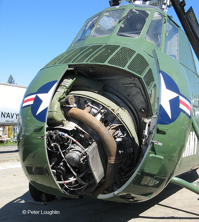
Radial can work at an angle, as well
h34-choctaw-pcam-03.jpg

All the way to horizontal, even. just makes ducting more difficult
 
Alvis had carried out a comprehensive reworking of the original Rhone et Ghome engine as had several other manufactures around the world with at least one reporting achieving as cruising power of 1,144 hp at a sustained 2400 rpm at an altitude of 14,764 feet. Now I am not saying that Alvis would categorically achieve this but it does give an indication of the potential of the basic design.

It goes without saying that I'd very much love to see that report.
Here is the table from the Flight magazine, December of 1939: link

When they installed (20mm to 35mm) motorkanon in WW2 fighters, they laid the cannon barrel in the V between cylinder banks of inline engines. The Messerschmitt 109 differed because it’s motorkanon lay on top of its inverted V engine.
All WW2 combat engines had propeller speed reduction unit that reduced rpms to keep propeller tips subsonic. The barrel does not need to fire through the crankcase because the PSRU can easily displace the prop shaft above the engine block.
Most PSRUs displace the prop shaft above the crankshaft because a higher thrust line allows a more efficient, larger diameter propeller. By the same token, a higher thrust line permits shorter and lighter undercarriage. That easy on an in-line engine but .... probably never attempted on a radial engine.
In the ‘Panic Fighter 1938’ thread, I suggested installing a motorkanon in a single-row radial engine. This requires rotating the engine 30 degrees, to keep the cannon barrel on the centreline. This fictitious variation of the Wright/Pratt & Whitney R-1820 would displace it’s prop shaft higher enough to route the cannon barrel between the top two cylinders ..... sort of an inverted version of the reduction unit installed in the M-18 Hellcat tank destroyer. Hellcats were about a yard lower than M4 Sherman tanks - powered by the same R-1820 engine - which ran the driveshaft straight forward, forcing the turret basket to be higher, et

Cannons between 15 and 37mm were installed as motorkanon in ww2 fighters and used operationally. Soviets even tested 45mm cannon in that fashion, and quickly abandoned the idea due to violent recoil, so violent that aircrfat internals started cracking.
Bf 109 also have had cannon barrel laid between the cylinder banks (picture). The only engine where the prop gun was installed above & outside (more or less) the engine was probably the Ranger V-770 (picture). It would've been interesting to see the DH Gipsy 12 engine with such a thing.
Barrels firing through crankcase was probably never tried, it would've wrecked internals once those start moving or rotating.
Inerted V12 engines were supposed to offer better view over the nose, and less exhaust gasses to blind pilot in time of low visibility or night. IMO, either layout was a trade-off. We can recall that Germans installed inverted V12 on a captured Spitfire, while Yugoslavs installed inverted V12 on a Hurricane; both coversions flew.
I'd love to see how would've the radial engine rotated 30 deg would've looked powering an aircraft.
Sherman and Hellcat were powered by R-975 (45 in diameter). The M6 heavy tank was powered by R-1820 (55 in). Both engines were supercharged. Granted, the installation of the intermediate gear on the M-18 was an excellent idea, too bad it was not used on the M3 already.
 

marathag

Banned
I'd love to see how would've the radial engine rotated 30 deg would've looked powering an aircraft.

The biggest problem will be vibration from the longer output shaft, something that the USAAF ran into with the various long nose, close cowling prototypes.
Now one thing that might be different, would be the OTL example had the gearcase self supporting from the engine itself, here, may be able to have support beam(s) to support the end, and prevent, or at least reduce, shaft whipping.
Bonus points for putting a cooling fan at the end, so maybe this is the way for low drag radials

With the tilt, the pilot would have excellent forward vision ahead, besides the room for cowl guns.

An added bonus is with the tilt, there is more room for intercooler and the ducting
 
Thanks for posting those illustrations of Me 109 and Bell XP-77.

I stand corrected on the Me 109’s motorkanon’s routing BETWEEN inverted V cylinder banks and BELOW the crankshaft.
WI Messerschmitt had installed the motorkanon and propeller ABOVE the crankshaft?
How far would the thrust line be above the original?
How much would that shorten MLG legs?
How much would that reduce landing accidents?

That XP-77 profile explains the unique canopy shape. Rumour has it that Bell’s XP-77 suffered poor airflow over its tail feathers because the canopy’s rear half was sloped too steeply.
WI Bell installed a more gently-sloped aft canopy?
How much would that improve airflow over the tail?

Perhaps I was not clear enough in explaining when I suggested ROTATING a single-row, Wright/Continental R-1820, radial engine 30 degrees about its crankshaft. The crankshaft would still be pointed straight ahead, but rotation would center a gap - between cylinders - top dead center.
Then an offset PSRU raises the thrust line (er propeller hub) above the crankcase, allowing installation of a Motorkanon through the - raised - propeller hub.
The PSRU would still be bolted to the crankcase, though there might be an extra - engine mount strut - running straight back to the firewall.

OTL For example the - modern - Pratt & Whitney PT6A turboprop’s engine mounts run all the way from the firewall to the PSRU because the primary goal is transmitting propeller loads directly to the fuselage.

The (fictional) offset spinner would project forward from the top edge of the round cowling The PSRU only has to be forward enough to ensure smooth cooling air to the top pair of cylinders.

We might install a cooling fan, but it would be behind the engine, pulling air towards cowling flaps. Cowling flaps would only be on the sides of the fuselage - like FW109 or Sea Fury.
 
Last edited:
Top